Published 27 July 2026 | S R Forgings Technical Desk, Ludhiana
Both products are steel studs with a head on one end. Both are described loosely on site as “shear studs.” They are not interchangeable, they are not designed to the same standard, and using one in place of the other is a specification failure — not a substitution.
A shear connector stud makes a steel beam and a concrete slab act as one composite member. A PSR stud stops a reinforced concrete flat slab from punching through around a column. Different force, different code, different geometry. This article sets out the sizes for each, and a clear rule for deciding which one a drawing actually calls for.
What a shear connector stud does
In composite construction, a steel beam carries tension in its bottom flange and a concrete slab carries compression above it. Left alone, the two slide against each other at the interface and behave as two separate members. Welding headed shear connector studs to the top flange locks that interface: the shank resists the horizontal shear, and the head provides the anchorage that stops the slab lifting off the beam.
The result is a single composite section with far greater stiffness and moment capacity than the bare steel beam. That is the whole reason composite floors can be shallower and lighter than an equivalent all-steel or all-concrete design.
Shear connector studs are covered by ISO 13918 (stud type SD) and by AWS D1.1 Clause 7 as Type B studs. Design of the composite member itself follows Eurocode 4 (EN 1994), BS 5950-3 or BS 5400-5, or IS 11384 in Indian practice.
What a PSR stud does
A PSR stud — punching shear resistor, also sold as a stud rail, shear stud rail, or double-headed anchor — never touches a steel beam. It works inside reinforced concrete.
Where a flat slab meets a column, the column tries to punch a cone-shaped plug straight through the slab. This two-way shear failure is brittle and gives almost no warning, and it is the governing check for most flat-slab floors. PSR studs are arranged in rails radiating outward from the column, crossing the potential failure cone and carrying the shear across it in direct tension.
The governing product standard is ASTM A1044, which covers two assembly types: single-headed studs welded to a structural steel base rail (Type 1), and double-headed studs crimped into a non-structural carrier or spot-welded to a plate (Type 2). Design follows ACI 318, EN 1992-1-1 Clause 6.4, or the equivalent national code.
The difference that actually matters: head area
This is the point most buyers miss, and it is written into the standard itself.
A shear connector stud’s head only has to resist uplift. Its head area is roughly 2.5 to 4 times the shank area — a modest cap. A PSR stud’s head has to anchor the full yield force of the shank directly into concrete, with no bond length to help it. ASTM A1044 therefore requires the head area to be at least 10 times the shank area.
Because area goes with the square of diameter, a ten-times area ratio means the head diameter must be at least about 3.2 times the shank diameter. A 12 mm PSR stud needs a head of roughly 40 mm. A 12.7 mm shear connector stud has a head of 25 mm. They do not look alike once you put them side by side.
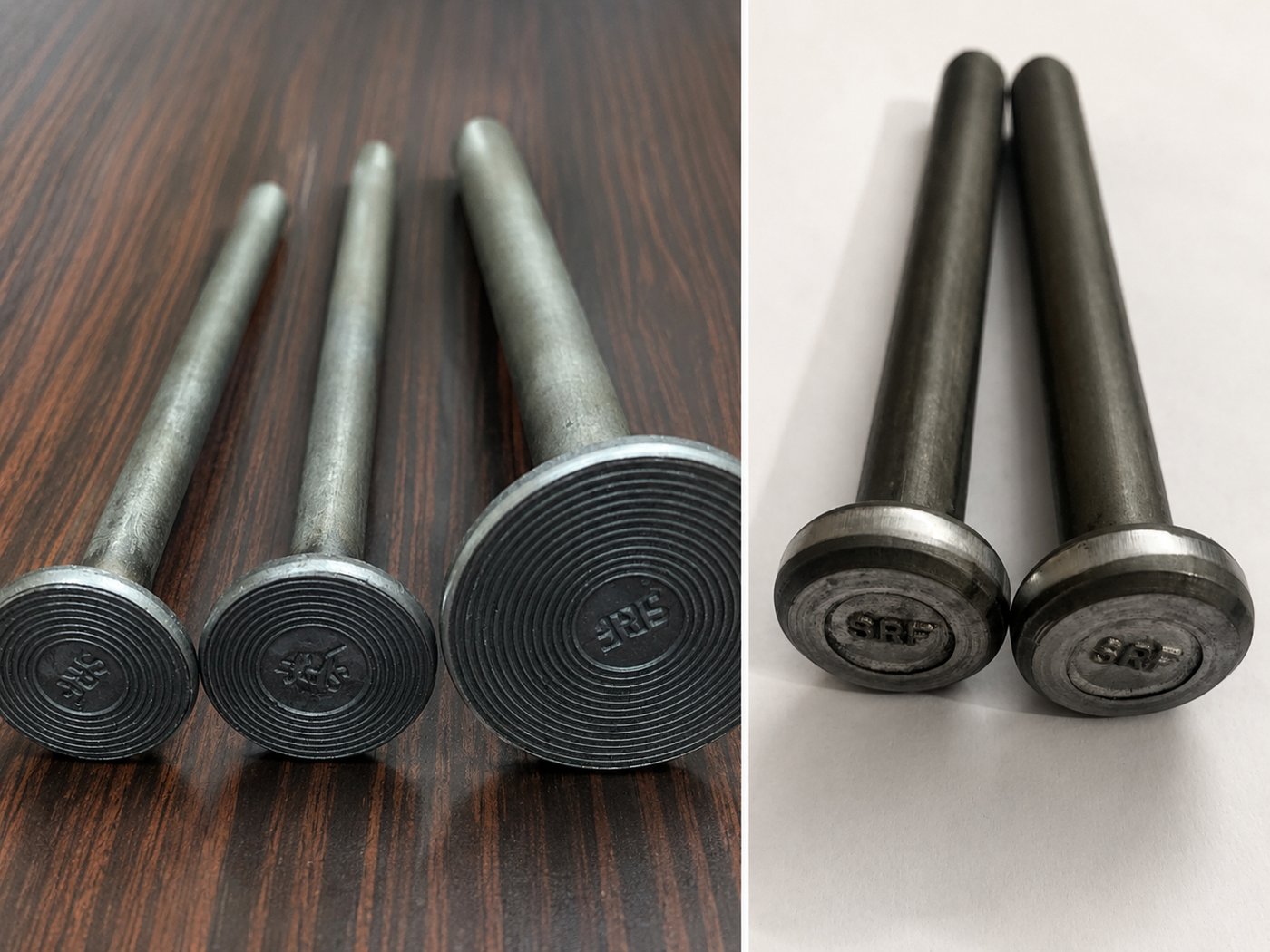
The head tells you which is which: a shear connector stud’s head is 2.5 to 4 times its shank area, a PSR stud’s is at least ten times.
ASTM A1044 states plainly that these stud assemblies are not intended for use as shear connectors in composite steel-concrete construction — and, running the same logic in reverse, an AWS D1.1 headed stud does not have enough head area to qualify as punching shear reinforcement. Ordering the cheaper composite stud for a stud-rail application produces an assembly that will not pass a code check.
Shear connector stud sizes (ISO 13918 type SD)
Nominal dimensions for the diameters in normal structural use. Head diameter d5, head thickness h3, weld collar diameter d3 and collar height h4 are as given in ISO 13918.
| Shank dia d1 (mm) | Head dia d5 (mm) | Head thk h3 (mm) | Collar dia d3 (mm) | Collar ht h4 (mm) | Burn-off (mm) |
|---|---|---|---|---|---|
| 10 | 19 | 7 | 13 | 2.5 | 3.0 |
| 13 | 25 | 8 | 17 | 3.0 | 3.0 |
| 16 | 32* | 8 | 21 | 4.5 | 4.0 |
| 19 | 32 | 10 | 23 | 6.0 | 4.5 |
| 22 | 35 | 10 | 29 | 6.0 | 5.0 |
| 25 | 41 | 12 | 31 | 7.0 | 5.5 |
* For shear applications the 16 mm head may be reduced to 29 mm. Imperial equivalents 9.5, 12.7 and 25.4 mm share the dimensions of the adjacent metric size. Weld collar dimensions are guidance values for flat position welding and do not apply to through-deck welding.
Standard lengths and weights
Lengths below are after weld (l2), which is the length the designer specifies. Mass is approximate, in kilograms per 1,000 pieces, at 7.85 kg/dm³. Expect 3–5% variance against theoretical weight because of manufacturing tolerance and tip geometry — worth allowing for when reconciling a bill of quantities against a delivered consignment.
| Length l2 (mm) | Ø13 | Ø16 | Ø19 | Ø22 | Ø25 |
|---|---|---|---|---|---|
| 50 | 8 | 12 | 16 | 20 | — |
| 75 | 10 | 16 | 21 | 28 | 37 |
| 100 | 13 | 20 | 27 | 35 | 47 |
| 125 | 16 | 24 | 33 | 43 | 57 |
| 150 | 18 | 28 | 38 | 50 | 66 |
| 175 | 21 | 32 | 44 | 58 | 76 |
| 200 | 23 | 36 | 49 | 65 | 85 |
| 225 | — | 40 | 55 | 73 | 95 |
| 250 | — | 44 | 60 | 80 | 105 |
| 275 | — | — | 66 | 88 | 114 |
| 300 | — | — | 72 | 95 | 124 |
Mass in kg per 1,000 pieces. Lengths to 350 mm are available in 19, 22 and 25 mm diameters. Intermediate and special lengths are made to order.
Before weld or after weld? The ordering trap
A shear stud gets shorter when it is welded. The arc burns off part of the shank and the molten metal forms the collar around the base. The stud you buy is length l1 (before weld); the stud on the structure is length l2 (after weld).
The burn-off column in the table above gives the difference for bare-steel welding: 3 mm at 13 mm diameter rising to 5.5 mm at 25 mm. Welding through profiled metal decking consumes more — allow roughly 10 mm rather than 5 mm, and check against a trial weld on the actual deck profile.
Designers specify after-weld length. Suppliers quote in before-weld length. If neither party says which, someone receives studs 5 mm short of the drawing. State it explicitly on the purchase order — for example: Stud ISO 13918 – SD1 – 19 × 100 (LBW), quantity, plus ferrules.
Ceramic ferrules
Shear connector studs use the UF ferrule family, sized to the stud: UF 13 for a 13 mm stud, UF 19 for a 19 mm stud, and so on. Two variants matter on site. The standard ferrule has 18 teeth and is used for welding directly to bare steel. The through-deck ferrule has 8 teeth, giving the larger vent openings needed to clear the gas and zinc generated when welding through galvanised decking.
Stud and ferrule are a matched system. Mixing a ferrule from one manufacturer with a stud from another is a common cause of inconsistent collar formation and should be avoided.
PSR stud sizes and rail configuration
PSR studs are supplied as assemblies, not loose pieces. The engineer specifies stud diameter, stud height, the number of studs per rail, the spacing along the rail, and the number of rails at each column. The manufacturer builds the assembly to that layout.
| Shank dia (mm) | Imperial | Min head dia (mm) | Typical use |
|---|---|---|---|
| 9.5 | 3/8 in | 30 | Thin slabs, light loading |
| 12.7 | 1/2 in | 40 | Typical flat-slab floors |
| 15.9 | 5/8 in | 50 | Heavy floors, transfer slabs |
| 19.1 | 3/4 in | 61 | Rafts, pile caps, high loads |
Minimum head diameter is derived from the ASTM A1044 requirement that head area be at least 10 times shank area. Metric shank diameters of 10, 12, 14, 16, 20 and 25 mm are also produced. Stud height is set by slab thickness less top and bottom cover.
Typical layout rules — always subject to the governing code and the project engineer:
- The first stud sits close to the column face, generally within about half the slab effective depth.
- Spacing along a rail is limited to a fraction of the effective depth, tightening as the applied shear stress rises.
- Rails radiate outward far enough that the concrete alone can carry the shear beyond the last stud.
- Peripheral spacing between adjacent rails is capped so no unreinforced wedge is left between them.
Compared with closed stirrups or bent-up bars, stud rails anchor more reliably (the head develops the bar directly rather than relying on a bend), fix far faster, and leave the top and bottom mats uncongested. Most codes also permit a higher limiting shear stress with headed shear stud reinforcement than with stirrups — which is often what allows a drop panel or column head to be deleted from the design.
Where to use shear connector studs
- Composite bridge decks — studs welded to the top flange of plate girders or rolled beams beneath the deck slab.
- Composite floors in commercial and high-rise buildings, welded through profiled steel decking.
- Industrial mezzanines and equipment platforms where a shallower floor depth is needed.
- Steel-concrete composite columns and encased beams.
- Metro and railway station structures, elevated corridors and flyover decks built in composite steel.
- Anchorage of concrete to steel embed plates and base plates.
Where to use PSR studs
- Flat slab and flat plate floors at internal, edge and corner columns.
- Post-tensioned flat slabs, where punching shear normally governs the slab depth.
- Raft foundations, pile caps and isolated footings under heavy column loads.
- Podium and transfer slabs carrying discontinued columns from the structure above.
- Slabs with openings close to a column, where the shear perimeter is reduced.
- Strengthening existing flat slabs where the original punching shear capacity is inadequate.
The quick decision
| Shear connector stud | PSR stud / stud rail | |
|---|---|---|
| Question it answers | Is there a steel beam under the slab? | Is there a concrete column through the slab? |
| Force resisted | Longitudinal shear at the steel-concrete interface | Punching (two-way) shear around a column |
| Welded to | Steel beam flange or through metal deck | A flat steel base rail, in the factory |
| Product standard | ISO 13918 (SD), AWS D1.1 Type B | ASTM A1044 |
| Design code | EN 1994, BS 5400-5, IS 11384 | ACI 318, EN 1992-1-1 Cl. 6.4 |
| Head area / shank area | About 2.5 to 4 | 10 minimum |
| Installed by | Site stud welding gun | Fixed into the rebar cage before pour |
Three mistakes that cost money
- Ordering shear connector studs for a stud-rail application because both were called “shear studs” on the enquiry. The head area will not comply with ASTM A1044 and the assembly will not pass review.
- Confusing before-weld and after-weld length, and receiving studs a full burn-off short of the drawing.
- Buying ferrules separately from the studs. Ferrule bore governs weld quality; a mismatched ferrule produces an inconsistent collar and failed bend tests.
About S R Forgings
S R Forgings manufactures headed shear connector studs to ISO 13918, PSR studs and stud rail assemblies, HSFG bolts, foundation and anchor bolts, ASTM A193 B7 and B7M stud bolts, DTI washers and engineered fasteners to customer drawings. The plant is at Focal Point, Ludhiana, Punjab, and the company has been in production since 2009, supplying domestic and export markets.
For sizes, material test certificates or a quotation:
- Phone: 0161-2671043 / 2220669
- Mobile / WhatsApp: +91 98763 35042
- E-615, Phase VII, Focal Point, Ludhiana 141010, Punjab, India
Note: dimensions in this article are nominal values from the referenced standards and are given for guidance. Always work to the governing project specification and the current edition of the applicable standard.